
OEM Chain Tensioner (fully assembled)
The timing chain tensioner is a critical component in the k-series engine, as it prevents the timing chain from loosening, which could result in fouled valve timing and possible engine damage. To understand why the chain tensioner is necessary, you need to understand what happens to the chain to make it stretch and/or loosen. When the sprocket on the crank rotates, it applies tension to the chain which forces the cam sprockets to rotate. The higher the rpm’s the motor is spinning at, the higher the tension that the chain is exposed to. The size of chain that is used on these motors is chosen to be strong enough to last for thousands of miles, while keeping the rotating mass of the motor as low as possible. If the chain were a smaller size, it wouldn’t last as long; if it were a larger size, the engine wouldn’t rev as quickly as it does. When enough tension is applied to a chain, it will stretch in two ways. The first type of stretching is known as elastic (temporary) elongation. In this situation the chain stretches while the tension is applied and returns to its original length once the tension is removed. The second type of of stretching is known as plastic (permanent) elongation. In this situation, the chain is permanently stretched. This stretches the chain as little as a few millionths of an inch at a time, but can add up after the engine is run for a few thousand hours. Plastic elongation will not occur until the chain has first been elastically elongated; this is because it takes more tension to plastically elongate a chain than to elastically elongate a chain. Timing chains can also loosen and tighten due to valve springs forcing cams to rotate. What all of this means is that the chain tensioner needs to be able to take up both the temporary and permanent slack in the chain.

Above is a chain tensioner that’s been cut in half, to expose all of the vital internal components. The tensioner in a k-series motor consists of 13 different parts. There are two assemblies in the tensioner that control the flow of oil through the tensioner as well as control the force the tensioner applies to the chain guide. There is also a ratcheting mechanism that allows the tensioner’s piston to move in and out, while preventing the piston from being pushed fully back into the tensioner, allowing the chain to become overly slacked. That ratcheting mechanism is shown below. It’s hard to make out in the image, but the ratcheting mechanism allows the piston to move in and out about .25″; this travel takes up the slack caused by elastic elongation in the chain. If the piston moves out of the tensioner more than this, it will ratchet to the next tooth, allowing the piston to move back into the tensioner about .25″, but no more. This is what takes up the slack caused by plastic deformation.

Shown below is one of the two valves mentioned earlier. This is just a simple check valve that is pressed into the chain tensioner. It allows oil from the engine to flow into the chain tensioner, but prevents it from flowing from the tensioner into the engine. It should be mentioned that the large spring shown inside the tensioner does not apply the majority of the pressure to the chain. This spring has a relatively small spring rate and is there primarily to apply pressure to the chain only when the oil pressure is low(during start up, idle, etc).

Shown below is the second of the two valves mentioned earlier. This valve is a high-pressure release valve that allows oil to flow out of the tensioner (which is sent to the chain through the chain guide). It takes about 100 PSI to engage this valve and allow oil to flow through it. The pressure provided by the engine is insufficient to flow oil through this valve; instead, it’s the force applied to the tensioner by the chain during high rpm’s that causes a pressure spike in the tensioner and consequently bleeds oil to the chain. When the chain is slack, however, the tensioner uses the oil pressure from the motor to extend the piston and press the chain guide tightly against the chain. It should be obvious by now that the engineers at Honda put a great deal of thought into their design and how it interacts with the timing chain under different loading conditions over the chain’s life span.


Now for the problem with Honda’s design (at least the problem that plagues anyone interested in running aggressive cams in a k-series motor). The problem is that the tensioner sees higher loads when certain after market cams and valve springs are used, due to different cam profiles and higher spring rates; this higher load wears out the teeth on the ratcheting mechanism used on the tensioner. If the teeth wear out enough, the piston can be pushed into the tensioner enough to cause slack in the chain and risk damage to the motor. In addition, the only thing that prevents the piston from rotating in the tensioner, thereby causing misalignment of the teeth in the ratcheting mechanism, is the groove in the chain guide that the tensioner piston fits into. In the cases we’ve observed, the fit between the piston and chain guide has been loose enough to allow the piston to rotate 5-10 degrees in either direction. This is more than enough to cause the ratcheting teeth to not line up well, and when the teeth don’t line up well, they wear much much faster. Couple this misalignment with the higher loads caused by aftermarket cams and springs, and you’ve got a recipe for disaster.
Don’t lose all hope though, because we’ve got something that’s actually designed for the beating you’ve been handing your now worn-out OEM unit.
So now that you know how the k-series motor’s chain tensioner works and what problems it has when you run aggressive cams, you’re probably wondering what we intend to do about it. Well, during the last six months or so, I’ve devoted a lot of time to cutting up broken and new OEM k-series chain tensioners and finding out what there is to them, and how they could be improved. My first discovery was that the internals of the tensioner were great. Honda’s engineers did an excellent job of controlling the pressure and oil flow through the tensioner, and there wasn’t a weak link to be found there. There was no sign of excessive wear or fatigue inside the tensioner. So I wanted to mimic the construction and dynamics of the OEM internals. I then turned my attention to the design of the piston itself and the design of the ratcheting mechanism. Shown below are pictures of the teeth on a broken tensioner piston vs. the teeth on a new one and the locking tooth from a broken tensioner and the locking tooth from a new one.


As you can see, the broken (or worn out, rather) tensioner’s teeth show very clear signs of wear on both the piston’s teeth and the pivoting locking tooth. Some wear would be expected from a part like this, but the worn out tensioner’s parts (as shown above) were so worn down that the ratcheting teeth didn’t engage anymore. This allowed the piston to be pushed completely into the tensioner. When a tensioner gets worn down to this point, any force it applies to the chain is done only by the spring and hydraulic assembly, so there arises ample opportunity for the chain to push the piston into the tensioner and become slack, possibly leading to motor damage.
Now is this simply a case of poor material selection on honda’s part? Some would disagree with me, but I’m going to say “no.” We have not been able to find any cases of chain tensioner failure in a well maintained, unmodified engine. So in that respect, the tensioners are only failing when they are subjected to forces greater than they were designed for. That said, there is a big contributing factor to the failure of these tensioners that has less to do with material choice and more to do with the fitment between the tensioner piston and the chain guide. As I stated in my article where I dissected the OEM tensioner, there’s a loose fit between the slot in the chain guide and the tip of the tensioner piston. This loose fit allows the tensioner piston to rotate several degrees. When the piston rotates (due to engine vibration, etc) and is then pushed back into the tensioner, engaging the locking tooth, the locking tooth and the teeth on the piston are not perfectly lined up (see illustration below).

This misalignment cause huge stress concentrations that fatigue the ratcheting mechanism much faster than if the teeth meshed correctly. Allow this to happen too much, and the ratcheting mechanism will be rendered completely ineffective like was seen in the worn tensioner showed earlier. Knowing all of this, I set out to design a bolt-on replacement for the OEM tensioner, that would not wear out like the OEM unit did when exposed to the increased forces (from the chain) associated with running aggressive cams and stiffer valve springs.
My first two design changes were aimed at the ratcheting mechanism and the fitment between the piston and chain guide. The piston was redesigned to make it press into the chain guide rather than loosely fit into it. This was intended to eliminate any rotation of the piston inside the tensioner. Having done this, the likeliness of wearing out the tensioner was reduced, but I wanted to make sure that you could beat the living daylights out of the tensioner and see almost no wear at all. With that goal set, I added a second ratcheting mechanism, identical to the first one. A computerized model of the tensioner (and more importantly the ratcheting mechanism) can be seen below. (Note: the image shown below is a cross section of the solid model and does not show all components).

The last (and arguably most important) step of the design phase was to select the materials for the tensioner. To avoid being overly pedantic, I’ll forgo listing the alloys and heat treatments I chose for the parts on this tensioner. However, I will note that for the ratcheting mechanism, we decided to go with some more robust materials, and use steel alloys similar to those found in the ratcheting mechanisms found in impact wrenches.
After thoroughly analyzing the design of the OEM K-series chain tensioner and determining the changes that needed to be implemented, it was time to fabricate some prototypes for testing. We had two units made, and are currently in the the preliminary stages of testing. The majority of testing will utilize skunk2 Stage 3 cams and pro-series valve springs. The engine will be run hard on the dyno, drag strip, and road course(s). We will also be daily driving the car, for extra measure. Like stated in my previous article on the chain tensioner, our unit uses tighter tolerances and high grade materials than the OEM tensioner, and it is these two elements, combined with a beefed up ratcheting mechanism, that will allow this tensioner to take the abuse it will see when used with the upgraded valve train we plan to run, as well as any other after market valve train meant for the k-series motor.
Developing this tensioner and sourcing the parts for it was a tremendous undertaking. Every part of it is custom manufactured to our specs. Even the springs it uses had to be custom wound to suit our application.
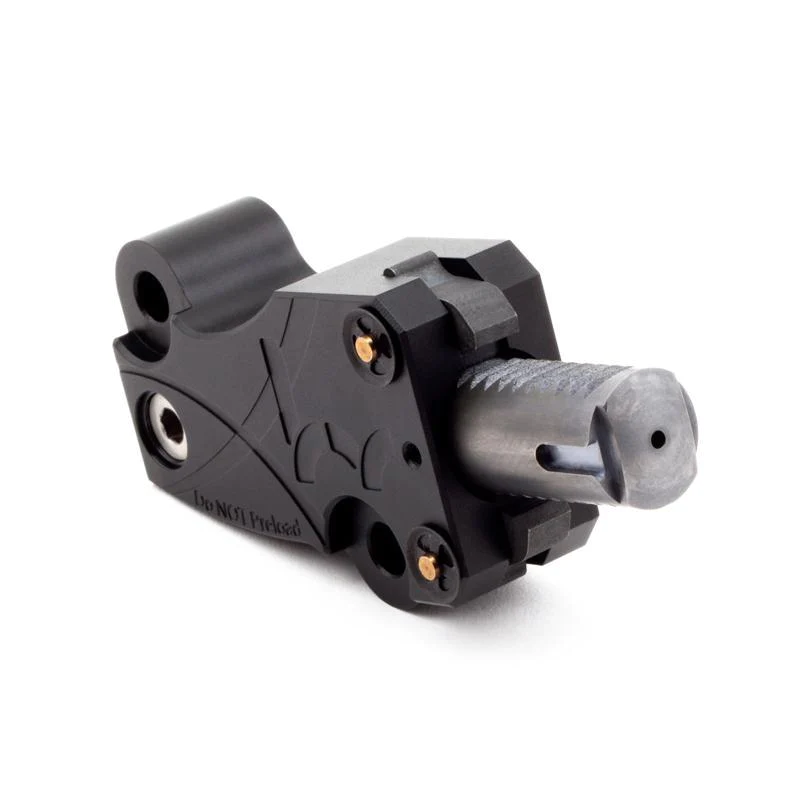
Shown below are some pictures of the tensioner before assembly, after assembly, and mounted to a motor.


Keep in mind that the production units will not look like the tensioner shown above. All of the features, materials, and tolerances will be identical, but the design will be a little easier on the eyes. Shown below are a few recent shots of the nearly completed production design. The body of the tensioner is 6061 aluminum that’s received a T6 heat treatment and a hard anodize (clear in the case of the prototype, and most likely black on the production units).