Hybrid Racing

Brandon Primes
Restore Your Classic Honda with Restotuner
Restoration can be a scary word. Especially when there is a lot of work to be done...- Mar 15, 2024
William Davidson
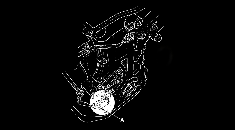
Wiring Guide: K20 to K24 Honda Crank Position Sensor Wiring
Navigate the complexities of K20 and K24 engine swaps with o...- Jun 1, 2023
- Tech Articles

David Cordell
How To Start Racing: Part 2
I want to bring you part two, for those who are more experienced and want to...- Apr 27, 2023
- Racing
David Cordell
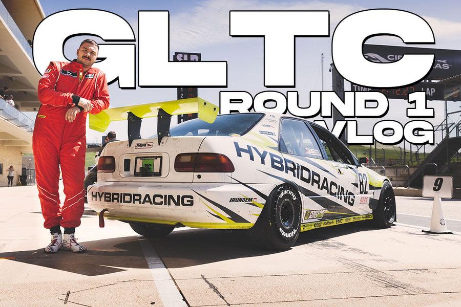
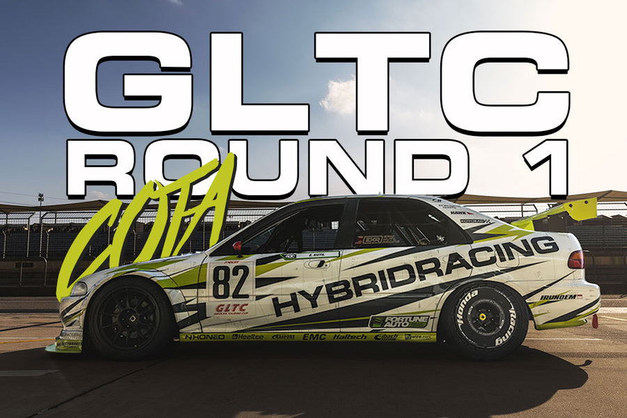
GLTC Round 1 VLOG!
Our recap from the first round of 2023 is here! Enjoy our first video series with ...- Apr 21, 2023
- Racing

David Cordell
FE1 Civic One Make Race!
We teamed up Street Metal & the Honda One Make race series in Thailand! ...- Mar 24, 2023
- Racing
David Cordell
Rollercoaster Weekend At Circuit Of The Americas!
Excitement level was off the chart and everyone has been extremely excited t...- Mar 16, 2023
- Racing
David Cordell
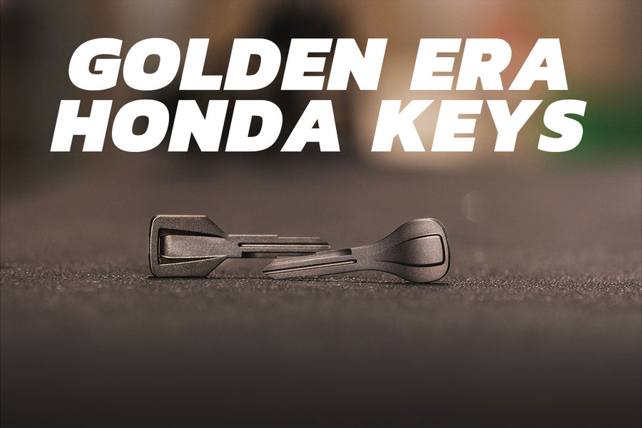
Hybrid Racing Golden Era Honda Keys
We know how important cars are. Spending thousands of hours and dollars on s...- Feb 24, 2023
- Buying Guides
- Tech Articles

David Cordell
The 2023 Civic Type-R is HERE!
After waiting a few months for the new FL5 Type-R's to ship, our car is fina...- Feb 15, 2023
- News & Events

David Cordell
A Look At Acura's Motorsports History
Endurance racing is one of the worlds toughest forms of motorsports. Even on a ...- Feb 2, 2023
Showing
1
of
24